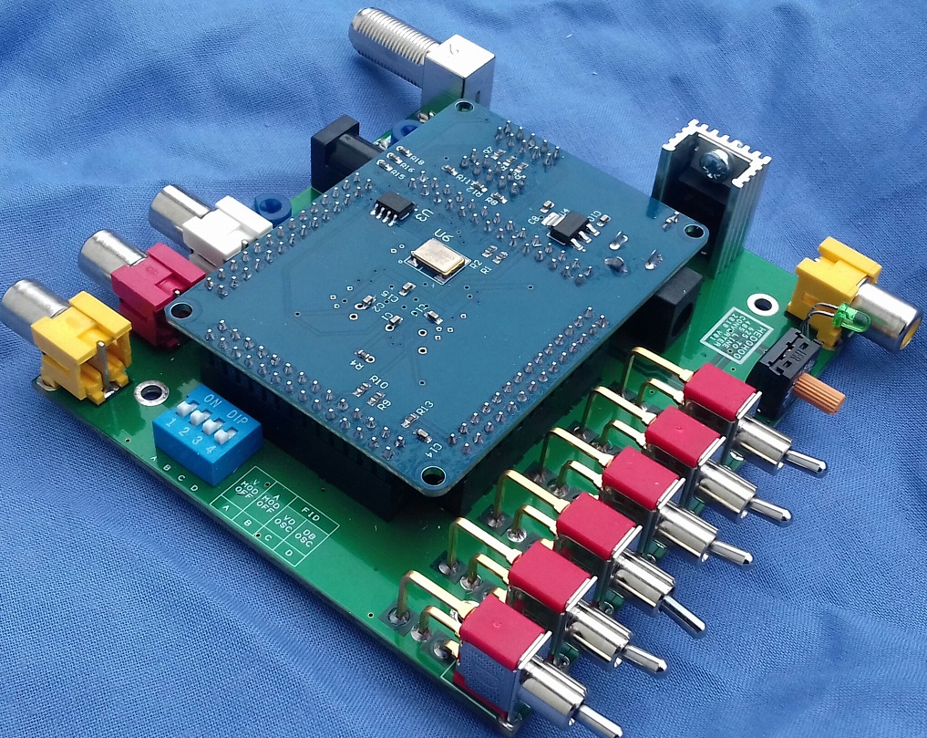
Hedghog is a homebrew 625 to 405 line standards converter based around a EP2C5T144 FPGA development board. On this page you will find the files required to build it.
All material including Downloads on these pages are provided 'as is' without warranty of any kind, either expressed or implied.
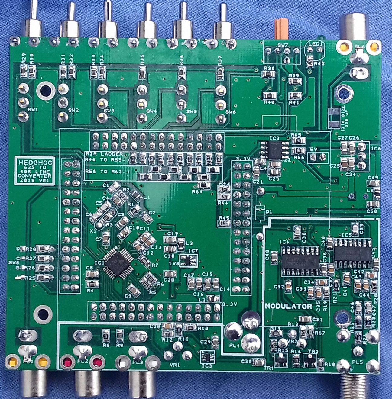
All Resistors, Capacitors and Inductors are 0805 size.
All Capacitors are ceramic multilayer types.
All Capacitors are rated at 6.3V or greater except C24 and C25
which must be 16V or greater.
Where given manufacturers part numbers are given as examples alternative parts may also suit.
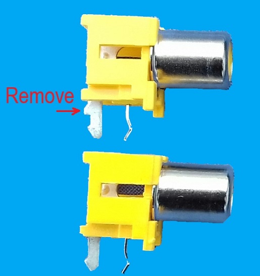
I can no longer source the phono sockets that I originally used. The one's that I use instead are in the parts list and need to be modified so they will fit the PCB. A spar on the rear leg needs to be filed flat see photo below.
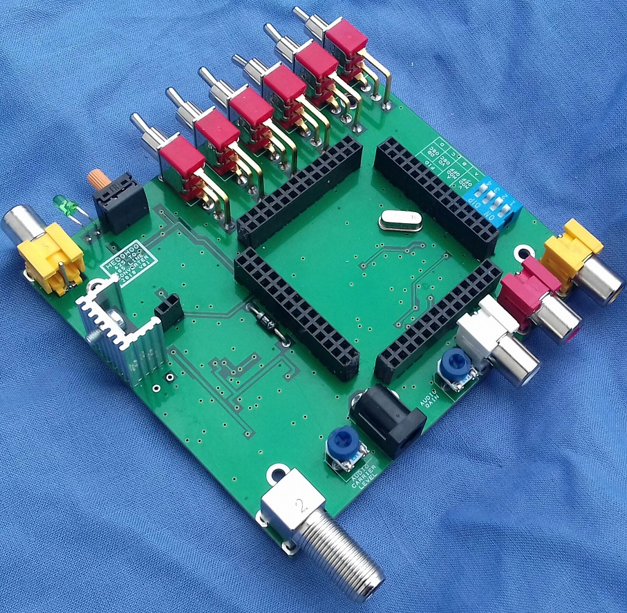
The PCB is double sided and measures 100 mm X 89.5 mm.
Link to uploaded Gerber files on PCBWay
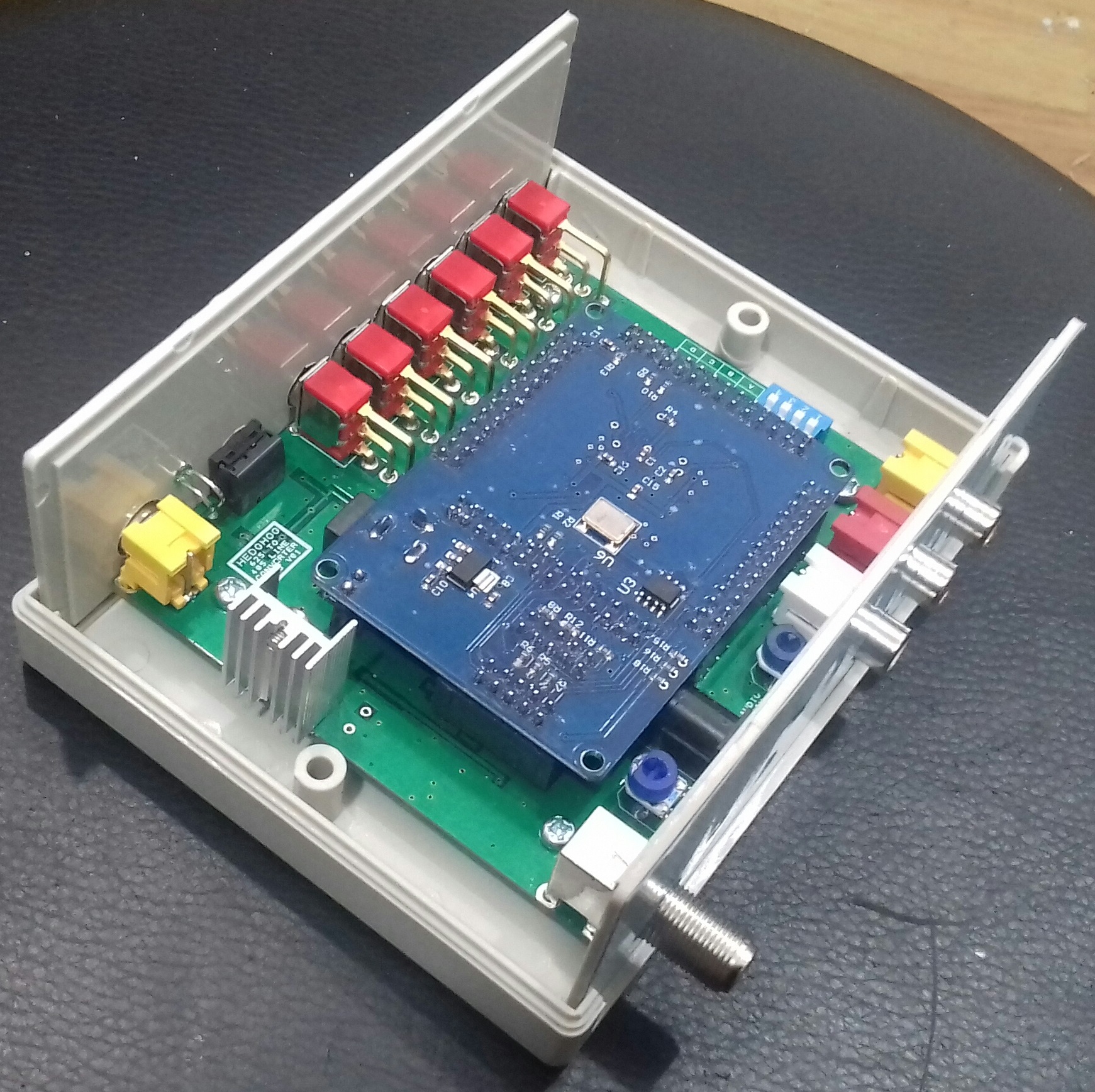
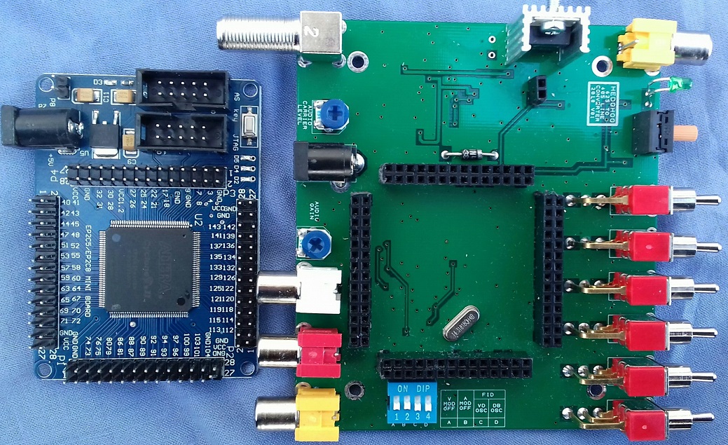
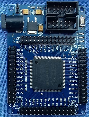
The FPGA board is a EP2C5T144. It has no Makers name or model apart from "EP2C5/EP2C8 MINI BOARD" . It is currently available from many sources and the photo below should help identify it.
Header P8 on the FPGA board supplies power (5V) to it. The FPGA board comes with this position empty so a male 2 pin 2.54mm header needs to be fitted. Header P8 can be seen in the top left corner in the photo below.
The FPGA board comes programed with a small program that makes the on board LED's D5, D4 and D2 flash in unison. When programed with the Hedghog program the three LED's flash but at different frequencies to each other. When installed in the Hedghog PCB this feature is disabled with the three LED's off.
If the Hedghog PCB is screwed into the Case don't attempt to insert or remove the FPGA board or the surface mounted components could get damaged.
The latest version of Altera's Quartus Prime does not support Cyclone II devices so an older version is required to program this FPGA board. I use Quartus II 13.0sp1.
Link to Quartus II 13.0sp1 download page
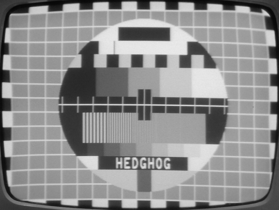
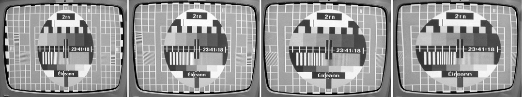
The converter has a built in test card loosely based on the Phillips PM5544. It has frequency gratings of 1, 1.5, 2, 2.5 and 3 MHz. In 5:4 mode the vertical castellations are cropped to keep the aspect ratio correct.
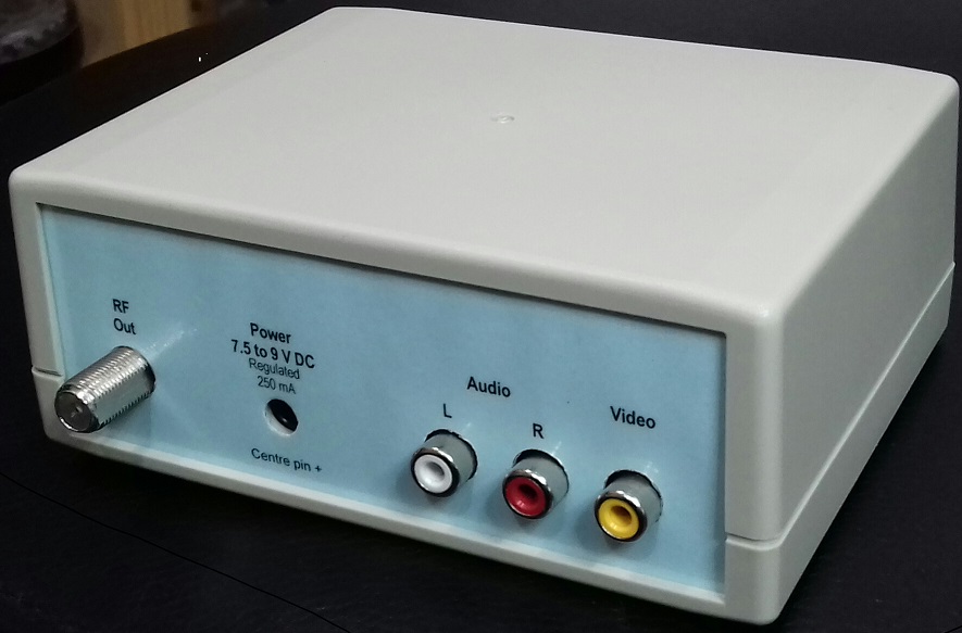
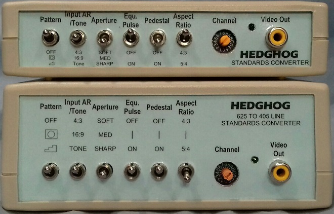
Golborne Vintage Radio Forum member Neutron suggested using the smaller Multicomp case MCRM2015S.This has proven popular so I have added legends suitable for this case.
 like the original ones they should print to the correct size. They are slightly smaller than the front and rear panels. I print them onto colored paper and then laminate it. Then cut them to size. The holes for the switches etc. can be cut with a scalpel. They will fit into the same slots as the front and rear panels, no glue required. The slots may need to be widened slightly.
February 2019: I updated the program so the converter can convert from 16:9 to both 4:3 and 5:4 as well as converting from 4:3 to 4:3 and 5:4.The new program file and legends to suit can be downloaded below.
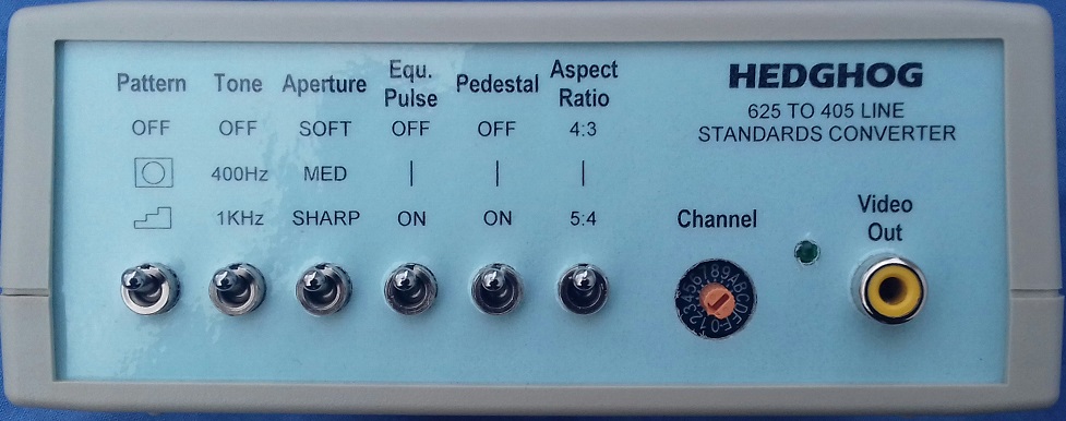
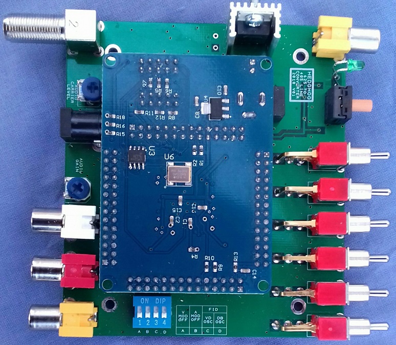
February 2019: This is the second update this month. The most noticeable change is that the DIP switch SW8-C now selects what the front panel switch SW2 function is.
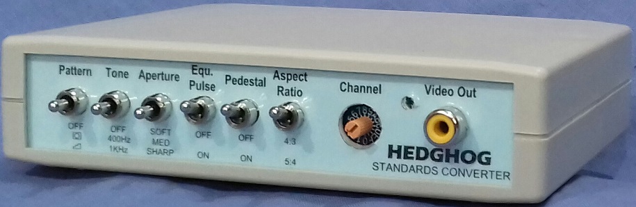
With SW8-C in the 'On' position SW2 selects between 400, 1000 Hz tone and tone off. SW8-D switches between 4:3 and 16:9 input. 'Off' = 4:3, 'On' = 16:9.
With SW8-C in the 'Off' position SW2 selects between 4:3, 16:9 and tone on. SW8-D switches between 400 and 1000 Hz tone.'Off' = 400 Hz, 'On' = 1KHz.
This version HEDGHOG_V04_02_2019 replaces both HEDGHOG_V02_09_2018(original) and HEDGHOG_V03_02_2019(16:9 input).
March 2019: Version V05 released.This rectifies slight misalignment of pedestal and non pedestal video. Enforced blanking before broad pulses has been removed. Added caption to the test card. Firmware version can now be viewed on screen by switching from grey scale to test card.
Circuit diagram (.pdf)
Component list (.pdf)
Component layout (.pdf)
Original front and rear panel legends (.pdf)
Original front and rear panel legends for small case (.pdf)
Front and rear panel legends to suit 16:9 input (.pdf)
Front and rear panel legends for small case to suit 16:9 input (.pdf)
FPGA program file (.jic)
Original thread on Golborne Vintage Radio Forum where Hedghog was born.
Hedghog review on Golborne Vintage Radio Forum.
Group Project: Building the Hedghog 405 standards converter on VRAT Fourm.
Doz' Blog:Building Frank C's Hedghog 625 PAL to 405 System A standards converter.
Thread on UKVRR Forum about Hedghog.