
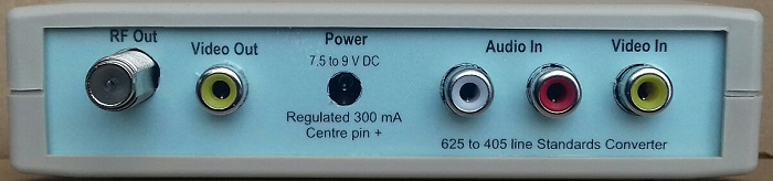
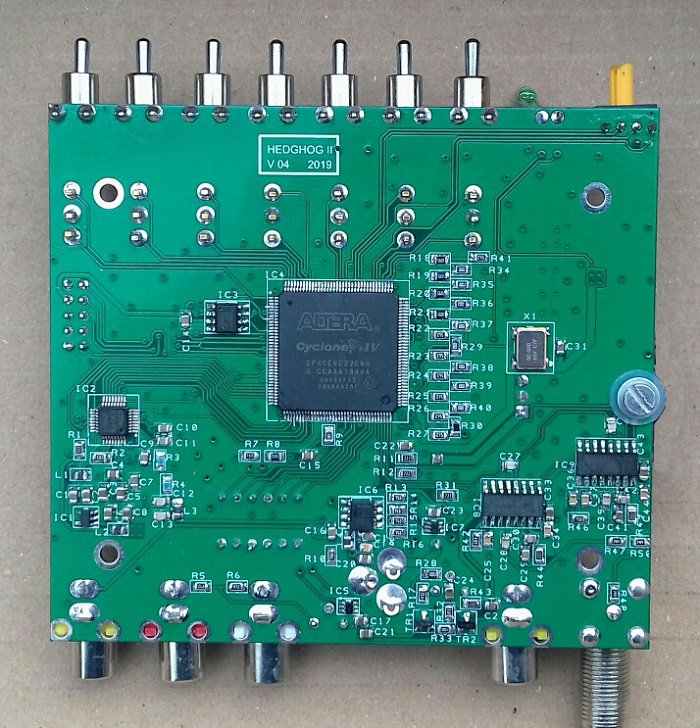
Hedghog II is a homebrew 625 to 405 line standards converter which is based on the Hedghog converter. On this page you will find the files required to build it.
All material including Downloads on these pages are provided 'as is' without warranty of any kind, either expressed or implied.
A Hedghog II has all the features of Hedghog with the following differences.
All Resistors, Capacitors and Inductors are 0805 size.
All Capacitors are ceramic multilayer types.
Where given manufacturers part numbers are given as examples alternative parts may also suit.
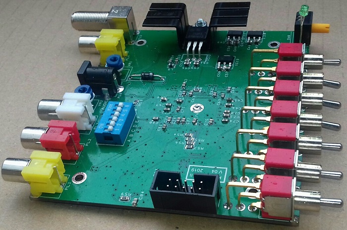
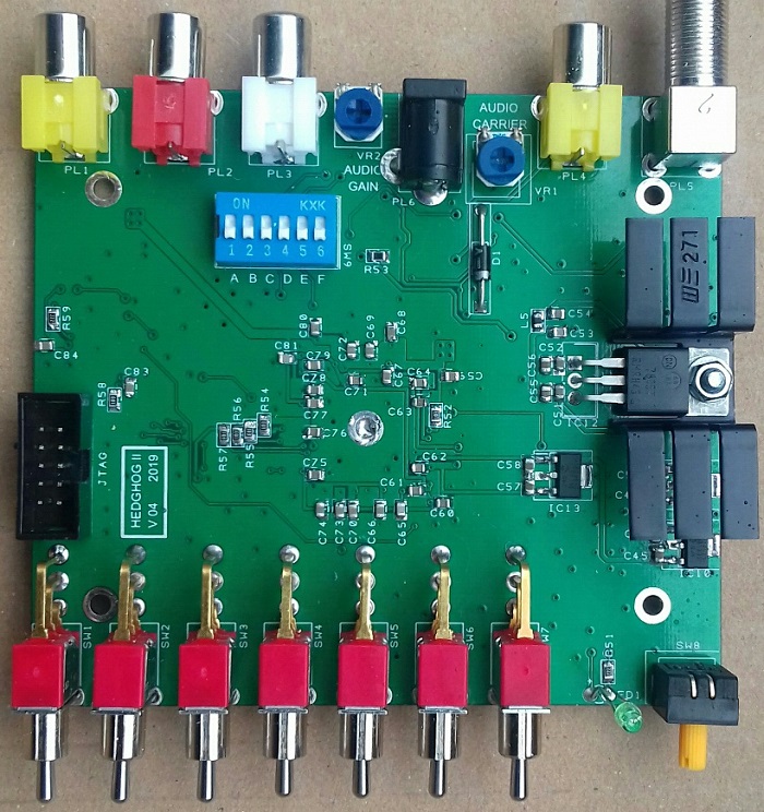
The PCB is double sided and measures 100 mm X 89.5 mm.
Link to uploaded Gerber files on PCBWay
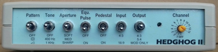
A: video modulator off.
B: audio modulator off.
C: Video clock check. LED flashes if OK.
D: 50 MHz clock check. LED flashes if OK.
E: Checks that a valid PAL signal is being received from the video decoder. LED flashes if OK.
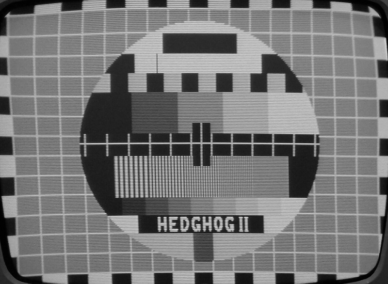
F: When on the 4:3 test card can be displayed even if the decoder is not present or not working.
Also when F is on the video port from the video decoder can be checked one bit at a time.
The bit being checked is selected by the HEX switch. 0 = bit0, 1 = bit1,......7 = bit7.
A flashing LED is good. LED continuously on is fail.
It checks if the bit is stuck high or low. or if the pin it is not connected.
It wont reliably show up if two adjacent pin are shorted together.
If DIP switch F is on video coming through the converter can be corrupted and rolling horizontally/vertically. This is normal.
As they all use the LED to display the result only one of the switches C to F can be on at a time. Otherwise the result will be unpredictable.
Added 405 line to 625 line conversion capability.
In August 2019 Jeffrey Borinsky successfully built a 625 to 405 standards converter. He detailed how he did it in a thread on Golborne Vintage Radio Forum. See link to the thread below.
The big thing was that he found a way to use a video decoder that was designed for 625/525 only to successfully acquire a 405 signal. This was a big development and has allowed me to write new firmware for Hedghog II which will allow it to convert from 405 to 625 as well as doing 625 to 405.
No change to hardware is required just a firmware upgrade.
With the new firmware the 625 to 405 converter works as before except for DIP switch 'E' is repurposed to be the 625 to 405/405 to 625 switch. Off being 625 to 405 and on 405 to 625.
In 405 to 625 mode the converted 625 video is available on the video out socket. The incoming 405 video is fed to the system A modulator so that it can be monitored on a 405 TV if required.
There are a couple of caveats.
Firstly I have no suitable VCR to record/playback 405 lines so I don't know how well it will preform with a VCR as source.
Second in order to get it to work I had to overclock the TVP5150. In 405 to 625 mode its data clock is close to 35 MHz which is well above its normal 27 MHz. This is well outside what it is designed for.
To date it has been tested in a number of Hedghog II and each one worked well with the TVP5150 showing no signs of distress or any sort of ill effect.
But as the TVP5150 is working so far outside its normal operating area no guarantee can be given firstly that every TVP5150 will work and secondly that if it does work that it wont be damaged.
In my opinion I think that the TVP5150 will be OK but as I have said above no guarantees. Only time will tell.
Circuit diagram (.pdf)
Component list (.pdf)
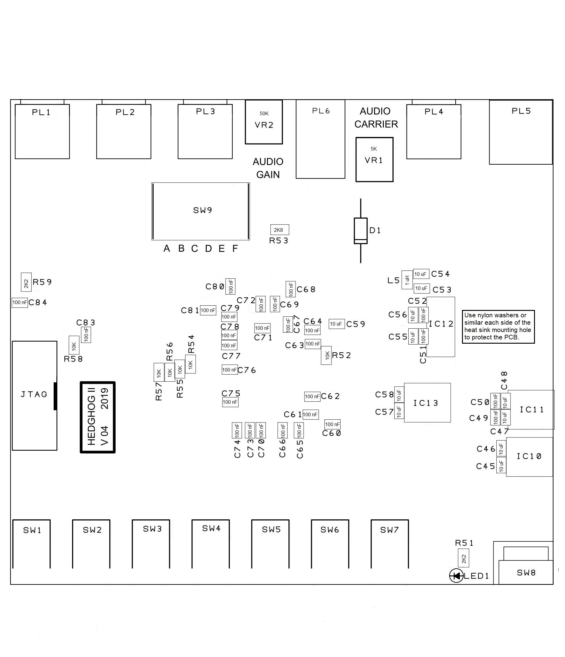
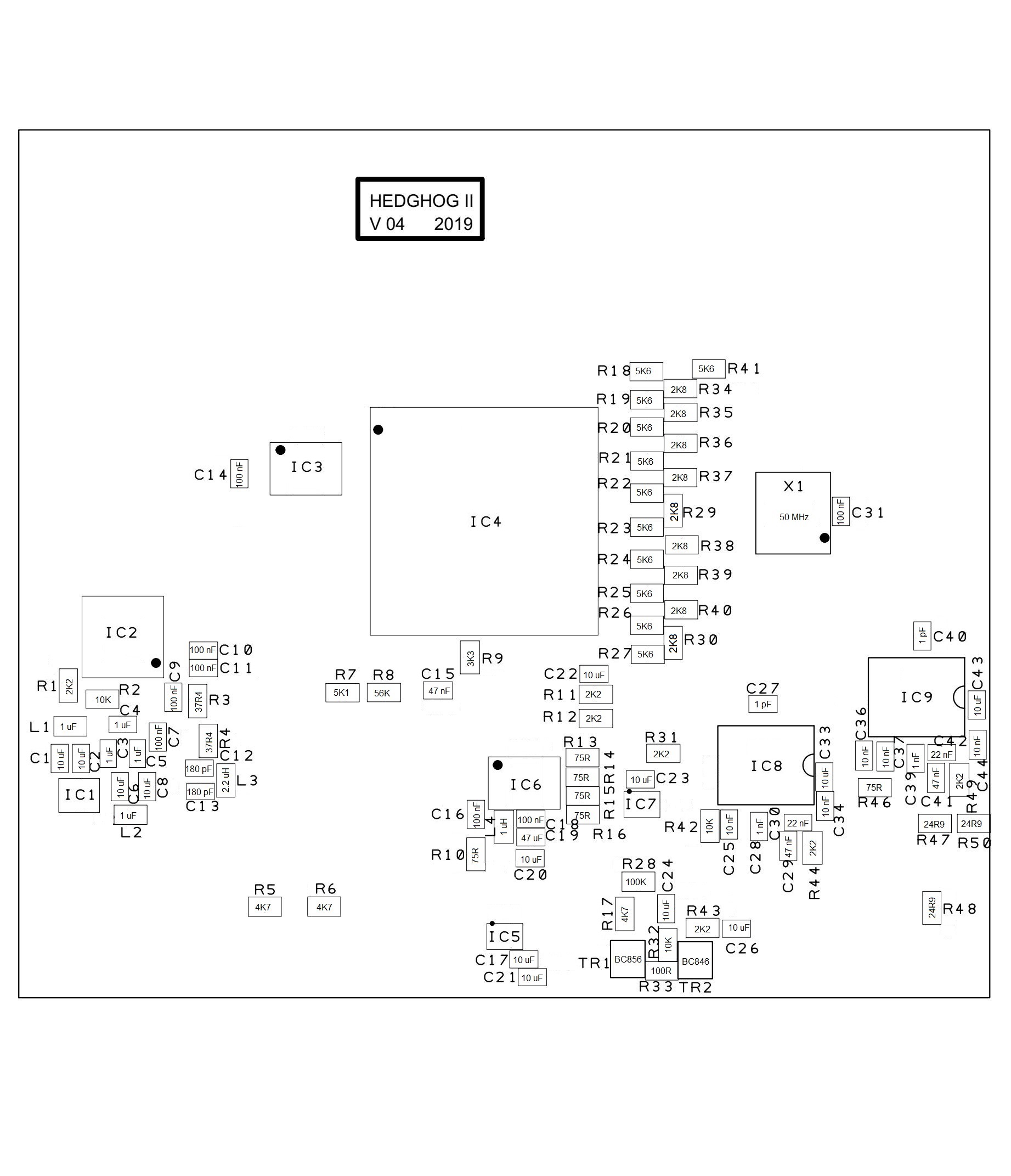
Component layout top (.jpg)
Component layout bottom (.jpg)
Front and rear panel legends (.pdf)
FPGA program file (.jic)
FPGA program file Dual Standards Converter (.jic)
Hedghog II thread on Golborne Vintage Radio Forum
Jeffrey Borinsky's 405 to 625 converter on Golborne Vintage Radio Forum.